Top 6 Steps to Diagnose Injection Pump Test Bench Flow Rate Inconsistency
Flow rate inconsistency is one of the most frustrating problems a diesel technician can face. When your injection pump test bench delivers different flow readings on the same pump—or shows unacceptable cylinder-to-cylinder variation—every calibration becomes suspect. Pumps that should pass are flagged as failures. Pumps that should fail slip through. And your workshop's reputation hangs in the balance.
The challenge is that flow rate inconsistency rarely has a single cause. It emerges from the interaction of multiple variables: fluid temperature, nozzle condition, pressure stability, speed control, measurement accuracy, and pump internal wear. Isolating the root cause requires a systematic, step-by-step approach.
Here are the top 6 steps to diagnose injection pump test bench flow rate inconsistency—and restore the precision your workshop depends on.
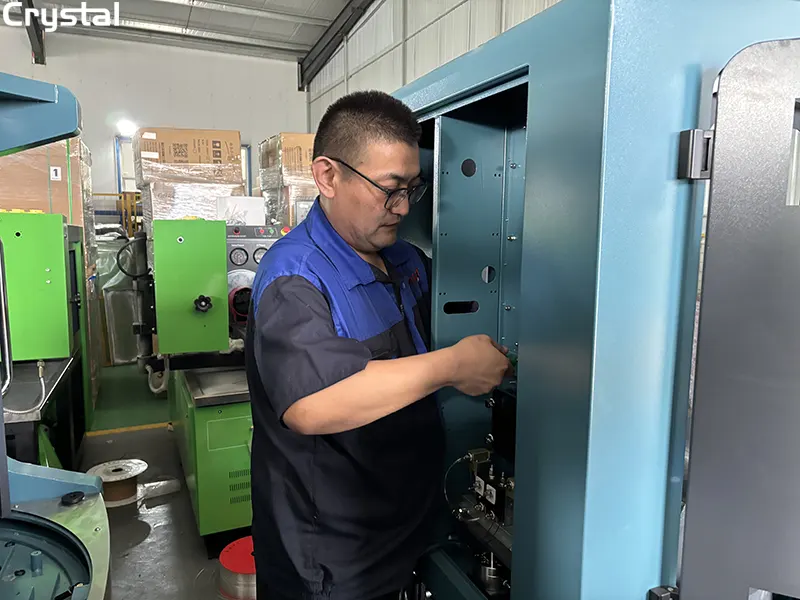
Step 1: Verify Test Oil Temperature and Viscosity
Temperature is the single most overlooked—and most influential—variable in flow rate measurement. Fuel viscosity changes with temperature, and viscosity directly affects flow rate through precision orifices.
Why Temperature Matters
Test oil that is too cold has higher viscosity, which restricts flow through the injector nozzle and produces artificially low readings. Test oil that is too hot has lower viscosity, which increases flow and produces artificially high readings. Even a deviation of a few degrees can introduce measurement errors of 5% or more.
What to Check
- Test oil temperature: Must be maintained at 40 ± 2°C for standard calibration procedures. Some specifications require 110°F–115°F (43°C–46°C) at the pump inlet.
- Temperature stability: The temperature must remain stable throughout the entire test sequence—not just at the start. Fluctuations during testing cause flow readings to drift.
- Temperature sensor calibration: Verify that the temperature sensor and display are accurate. A miscalibrated sensor can cause the system to maintain the wrong temperature.
- Heating and cooling system function: Check that the heating valve opens and closes properly. If the system cannot maintain temperature, flow inconsistency will follow.
The Fix
If temperature is the issue, allow the test bench to reach stable operating temperature before taking any measurements. Run the pump at full load position for several minutes until the calibrating oil has warmed up. Verify the temperature reading against an independent reference thermometer.
Crystal Advantage: Crystal injection pump test benches feature integrated temperature control systems with digital displays, allowing operators to monitor and maintain calibration fluid temperature precisely within the required range. The system supports temperature control at 40±2°C as standard.
Step 2: Inspect Test Nozzles and Injectors
Test nozzles and injectors are the reference point for all flow measurements. If they are worn, dirty, or inconsistent, every reading is compromised.
Why Nozzle Condition Matters
Test nozzles are precision components with microscopic orifice openings. Over time, these orifices wear, enlarge, or become partially blocked by contaminants. A worn nozzle flows more fuel than it should, while a partially blocked nozzle flows less. When different nozzles on the same test bench have different flow characteristics, cylinder-to-cylinder inconsistency is inevitable.
What to Check
- Orifice size and condition: Test stand injector nozzles must include a 0.020 in. (0.5 mm) orifice plate. Check for wear, erosion, or blockage.
- Spray pattern: A proper nozzle produces a consistent, well-defined spray pattern. Distorted or uneven spray indicates wear or contamination.
- Opening pressure: Standard test injectors should maintain an opening pressure of 17.5 MPa. Drift beyond this specification requires adjustment or replacement.
- Nozzle-to-nozzle variation: Compare flow readings across all test positions. If one position consistently reads high or low regardless of the pump being tested, that nozzle is the problem.
- Cleanliness: Carbon deposits, varnish, or particulate contamination can partially block nozzle orifices and cause inconsistent flow.
The Fix
Clean or replace suspect nozzles. Bosch specifies that test nozzles must be in perfect condition at all times, or the pump cannot be calibrated properly. If cleaning does not restore consistent flow, replace the nozzle assembly.
Crystal Advantage: Crystal test benches support testing of up to 12 cylinders simultaneously, with individual flow measurement for each position. This makes it easy to identify a single problematic nozzle by comparing flow readings across all positions.
Step 3: Check Supply Pressure and Fuel Delivery System
Flow rate is directly affected by the pressure and volume of fuel delivered to the pump under test. If supply pressure fluctuates or is insufficient, flow readings will be inconsistent.
Why Supply Pressure Matters
The injection pump requires a steady, air-free supply of fuel at the correct pressure. If supply pressure drops, the pump may starve at high speed, causing flow readings to fall. If supply pressure is too high, internal leakage increases, causing flow readings to rise. Either way, inconsistency results.
What to Check
- Supply pressure: Must be maintained at 0.3 to 0.5 bar gauge pressure at the pump inlet. Verify with a calibrated pressure gauge.
- Air in the fuel system: Air bubbles in the test fluid cause erratic delivery and unstable readings. Bleed the system thoroughly before testing.
- Fuel filter condition: A partially clogged filter restricts flow and causes pressure drops at high demand.
- Suction strainer: A blocked suction strainer can cause cavitation, which introduces air into the system and destabilizes flow.
- Return line: Ensure the return line is not restricted or drawing air back into the tank.
- Fuel line diameter and length: Test injector lines must be 0.093 in. (2.36 mm) inside diameter and 25 in. (63.5 cm) long. Incorrect lines affect flow characteristics.
The Fix
Bleed the system to remove all air. Replace clogged filters and clean the suction strainer. Verify supply pressure with an independent gauge. Ensure all fuel lines meet specification.
Crystal Advantage: Crystal test benches feature integrated priming and bleeding systems that simplify air removal. The digital pressure display allows real-time monitoring of fuel supply pressure, ensuring air-free delivery at the correct pressure.
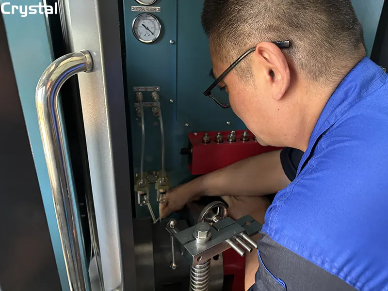
Step 4: Verify Pump Drive Speed Stability
Speed stability is fundamental to accurate flow measurement. A test bench must maintain a constant drive shaft speed for fuel pump calibration—and also be able to rapidly increase or decrease that speed for determining governor response.
Why Speed Stability Matters
Flow rate is directly proportional to pump speed. If the drive speed fluctuates during a test, the flow readings will fluctuate with it. Even minor speed instability—vibration, oscillation, or inconsistent ramp-up—can render test results unreliable.
What to Check
- Speed accuracy: Verify the tachometer reading against an independent reference. A miscalibrated tachometer causes the pump to run at the wrong speed, producing incorrect flow readings.
- Speed stability under load: The speed should remain constant when the pump is loaded. If speed drops under load, the drive system may be weak or the motor may be undersized.
- Drive coupling condition: Check for wear, backlash, or looseness in the coupling between the test bench drive and the pump. A worn coupling introduces speed variations.
- Belt tension (if applicable): Loose or worn drive belts can cause speed fluctuations.
- Frequency converter function: On modern benches with frequency conversion speed regulation, verify the converter is operating correctly.
The Fix
Tighten or replace worn couplings. Adjust or replace drive belts. Verify tachometer calibration. If the motor is undersized for the pumps you test, consider upgrading to a higher-power model.
Crystal Advantage: Crystal's 12PSB series test benches feature advanced frequency conversion speed regulation technology with a speed range of 0–4,000 RPM. The system provides precise, stable speed control across the full operating range, ensuring consistent flow measurements.
Step 5: Check the Flow Measurement System
The flow measurement system—flow meters, sensors, and collection vessels—is the final link in the measurement chain. If any component is inaccurate or inconsistent, flow readings will be wrong.
Why Measurement Accuracy Matters
Flow meters drift over time. Collection vessels may have inaccurate graduations. Sensors may lose calibration. Even the method used to read the measurement—meniscus position, timing, temperature correction—can introduce variability.
What to Check
- Flow meter calibration: Verify the flow meter against a known reference. Modern test benches achieve flow measurement accuracy of 0.1 ml; if your readings vary by more than this, calibration is suspect.
- Flow meter cleanliness: Contamination in the flow meter can cause sticking or inaccurate readings.
- Collection vessel accuracy: Check graduations against a calibrated reference. Replace worn or damaged vessels.
- Measurement procedure consistency: Ensure all technicians use the same procedure for reading flow—same timing, same meniscus reading, same temperature correction.
- Sensor connections: Loose or corroded connections can cause erratic readings.
- Software calculation: Verify that the test bench software is using the correct conversion factors and correction algorithms.
The Fix
Calibrate or replace suspect flow meters. Standardize measurement procedures across all technicians. Verify software settings. Implement a regular calibration schedule for all measurement components.
Crystal Advantage: Crystal test benches are equipped with high-precision flow meters that deliver accurate fuel quantity measurement, which is critical for generating valid correction codes and performance assessments. The CR918-PRO's precision flow meter delivers high repeatability, stable readings, and traceable accuracy.
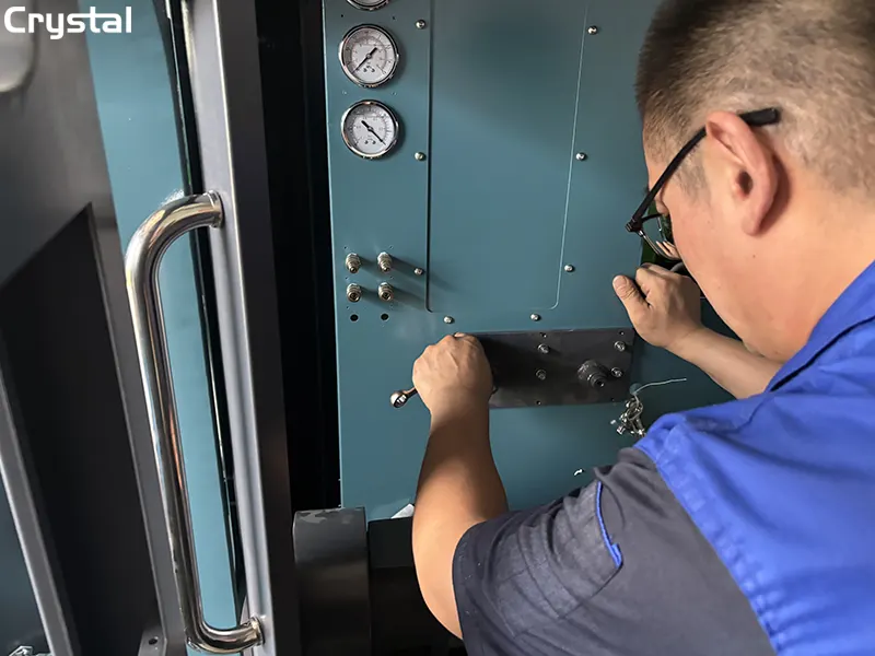
Step 6: Evaluate Pump Internal Components
If all external variables—temperature, nozzles, supply pressure, speed, and measurement—have been verified and flow inconsistency persists, the problem is likely inside the pump itself.
Why Internal Wear Matters
Worn plungers, damaged delivery valves, and degraded seals cause cylinder-to-cylinder flow variation that no amount of external calibration can fix. The test bench is accurately measuring an inaccurately performing pump.
What to Check
- Cylinder-to-cylinder delivery balance: At full load, variation between cylinders should not exceed 3%. At low idle, variation should not exceed 12%.
- Plunger and barrel condition: Worn plungers allow fuel to bypass the pumping chamber, reducing delivery. If a plunger displays pressure below 300 bar, replacement is recommended.
- Delivery valve function: A faulty delivery valve allows pressure to leak back, reducing flow. Check for dirt, sticking, or damaged gaskets.
- Column plug tightness: A loose column plug can cause inconsistent delivery in one cylinder.
- Seal condition: Worn or damaged seals allow internal leakage, reducing effective delivery.
- Cam and roller wear: On CP4 pumps, roller shoe follower seizure can cause catastrophic wear and flow loss.
The Fix
Perform a diagnostic test to isolate the problem. With the pump stationary, operate the test bench's transfer pump. Remove the bleed screw on the injector. If oil continuously drips, the delivery valve is stuck or the spring is broken. Replace or repair faulty components as needed.
Crystal Advantage: Crystal test benches can measure high-pressure maintenance power for each section, making it easy to identify which cylinder is underperforming. The system evaluates plunger condition by comparing delivery efficiency across the full pressure range.
Summary: The 6 Diagnostic Steps at a Glance
| Step | What to Check | Key Specification | Common Finding |
|---|---|---|---|
| 1. Temperature | Test oil temperature and stability | 40±2°C or 110°F–115°F | Unstable temperature causes 5%+ error |
| 2. Nozzles | Orifice size, spray pattern, opening pressure | 0.020 in. orifice, 17.5 MPa | Worn nozzles cause cylinder variation |
| 3. Supply Pressure | Pressure, air, filters, lines | 0.3–0.5 bar, air-free | Air causes erratic delivery |
| 4. Speed Stability | RPM accuracy, coupling, drive | 0–4,000 RPM range | Speed fluctuation = flow fluctuation |
| 5. Measurement | Flow meters, vessels, procedure | 0.1 ml accuracy | Drift causes inconsistent readings |
| 6. Pump Internals | Plungers, valves, seals | 3% max variation at full load | Worn components need replacement |
The Crystal Automation Advantage
Crystal Automation's injection pump test benches—including the 12PSB series and CRS1000 series—are engineered to eliminate the variables that cause flow rate inconsistency.
Precision Temperature Control
The 12PSB series maintains test oil temperature at 40±2°C with integrated heating and cooling systems. Digital displays allow real-time monitoring.
High-Accuracy Flow Measurement
Crystal test benches feature high-precision flow meters with 0.1 ml accuracy and a flow testing range spanning 0–600 ml per 1,000 injections.
Stable Speed Control
Advanced frequency conversion speed regulation provides precise, stable speed control from 0 to 4,000 RPM—eliminating the speed fluctuations that cause flow inconsistency.
Multi-Cylinder Testing
With support for up to 12 test cylinders, Crystal benches make it easy to identify a single problematic nozzle or a pump cylinder that deviates from specification.
Durable Construction
Test and waste oil tanks crafted from industrial-grade 304 stainless steel provide maximum corrosion resistance. A sophisticated three-stage filtration system prevents contamination.
Comprehensive Data Management
The built-in industrial computer system with 17-inch color LCD touch screen displays up to 6 test data sets simultaneously, making it easy to compare results and identify inconsistencies.
Conclusion
Flow rate inconsistency on an injection pump test bench is not a single problem—it's a symptom with multiple potential causes. By following these 6 diagnostic steps—verifying temperature, inspecting nozzles, checking supply pressure, validating speed stability, confirming measurement accuracy, and evaluating pump internals—you can systematically isolate the root cause and restore your bench to peak performance.
The key is order. Start with the simplest, most common causes (temperature and nozzles) before moving to more complex issues (pump internals). Document your findings. And maintain your equipment consistently to prevent problems before they occur.
With a Crystal Automation test bench and a disciplined diagnostic approach, flow rate inconsistency becomes a manageable challenge—not an insurmountable obstacle. Your customers depend on accurate calibration. Your reputation depends on precision. And your test bench is the foundation of both.
Written by
Taian Crystal Automation Co., Ltd.
Editor Chen
www.crystalautotest.com
WhatsApp:+86 185 9528 8526
Email:martin@crystalautotest.com
- HCR708 Comprehensive Test Bench Enters South African Market---Injecting New Momentum into Africa Diesel Repair Industry
- Best Injection Pump Test Bench Filter Cleaning Guide – 7 Tips to Prevent Circuit Contamination
- Injection Pump Test Bench Flow Accuracy: 7 Calibration Steps to Avoid Costly Errors
- The 10 Important Considerations for Troubleshooting High-Pressure Common Rail Test Benches

Crystal Automation is a leading Chinese manufacturer of common rail test benches and fuel injector test benches.