Top 6 High-Pressure Pump Diagnostic Methods on an Injection Pump Test Bench
Modern high-pressure common rail pumps operate at extreme pressures—up to 2,500 bar and beyond—with extremely tight internal clearances between piston and cylinder assemblies. These conditions make the pumps susceptible to wear, and when they degrade, the consequences cascade through the entire fuel system: poor atomization, incomplete combustion, power loss, and potential engine failure.
The most reliable way to diagnose high-pressure pump condition is to remove it from the engine and test it on a dedicated injection pump test bench. Unlike on-engine diagnostics—which are limited by variables like fuel quality, temperature, and driving conditions—a test bench provides a controlled, repeatable environment where every parameter can be measured against known specifications.
Here are the top 6 diagnostic methods used on a modern injection pump test bench to evaluate high-pressure pump condition and identify failure modes.
1. Flow Efficiency Test at Multiple Pressure Points
The flow efficiency test is the foundation of high-pressure pump diagnostics. It measures the pump's ability to deliver fuel at specific pressures and compares the results against a known-good reference pump.
How the Test Works
The procedure follows a specific sequence. The first stage involves evaluating the pump's flow at null pressure, followed by evaluation of its maximal delivery at 100 MPa. The obtained values are then compared to the values achieved by a new pump. The effect of a negative evaluation on the test bed is the disassembly of the pump, verification of the condition of its parts, and replacement of the damaged elements.
What the Results Reveal
Research conducted on both new and used pumps found that the highest difference in delivery exists at the maximal compression pressure. This means that testing at maximum pressure is the most sensitive indicator of wear—a worn pump may still deliver acceptable flow at low pressure but fail dramatically at high pressure.
Key data: A healthy pump should deliver 80 to 85 ml per 1,000 strokes at its rated pressure. A pump delivering less than 60 ml per 1,000 strokes should be considered for replacement.
Common Failure Modes Detected
- Gradual wear of plunger-barrel assemblies
- Delivery valve leakage
- Internal seal degradation
- Fuel control actuator inefficiency
Crystal Test Bench Advantage
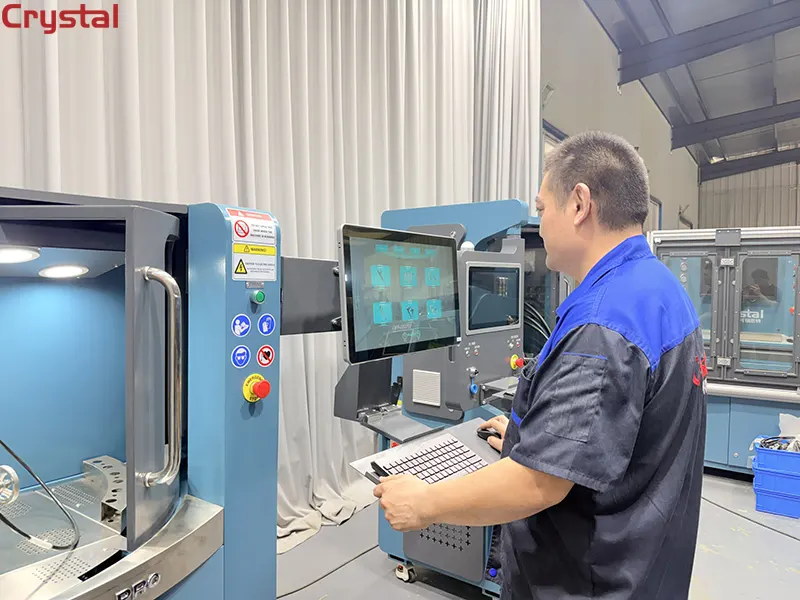
Crystal test benches measure pump output, discharge rate of the valve, and high-pressure maintenance power for each section. The system automatically evaluates whether a pump meets OEM specifications or requires repair.
2. Pressure Decay Test (Static Leakage Test)
The pressure decay test is the most direct method for detecting internal leakage in a high-pressure pump. It isolates the pump's high-pressure circuit and measures how quickly pressure drops when the pump is stopped.
How the Test Works
The pump is pressurized to its operating pressure, and then the drive is stopped while the pressure is monitored. The rate of pressure drop indicates the severity of internal leakage. A normal pressure decay should be less than 5% per minute at operating pressure.
On a common rail system, after reducing the pump fuelling to zero output, the pressure in the fuel system will begin to decay by natural leakage. The ECM or test bench software monitors this decay rate to determine pump health.
What the Results Reveal
A pressure decay rate exceeding 10% per minute indicates significant internal leakage. The source can be isolated by performing the test with the delivery valve blocked—if pressure still drops, the leakage is in the plunger-barrel assembly; if pressure holds, the delivery valve is the culprit.
Critical Note on Temperature
Test fluid temperature affects this test significantly. Fluid above 80oF (27oC) will tend to reduce the decay time, while temperatures below 80oF will increase it. This is why temperature control on the test bench is non-negotiable—a deviation of just a few degrees can introduce measurement errors of 5% or more in pressure decay readings.
Crystal Test Bench Advantage
Crystal test benches feature integrated temperature control systems with digital displays, allowing operators to maintain calibration fluid temperature precisely within the required range. The system automatically monitors pressure decay and generates pass/fail results based on OEM specifications.
3. Return Flow (Back Leakage) Measurement
Return flow measurement—also called back leakage or leak-off testing—is one of the most valuable and conclusive test procedures for diagnosing common rail diesel systems. It measures the volume of fuel that bypasses the pumping elements and returns to the tank.
How the Test Works
The pump is operated at specified pressure and speed, and the return flow is collected and measured over a defined period. The test bench measures both the delivery flow (fuel going to the rail) and the return flow (fuel returning to the tank). The total fuel entering the pump is determined by delivery + return flow.
What the Results Reveal
Excessive return flow indicates internal wear—fuel is escaping past worn plungers, damaged seals, or compromised delivery valves rather than being delivered at pressure. A pump with return flow exceeding 20% of total input is typically considered worn and may require repair.
Common rail test equipment measures injection and leakage (returning) quantity as a standard diagnostic parameter. The back leak flow measurement is a primary indicator of pump condition.
Common Failure Modes Detected
- Worn plunger and barrel assemblies
- Damaged delivery valve seals
- Fuel control actuator (IMV/MPROP) internal leakage
- Pressure regulating valve (DRV) malfunction
Crystal Test Bench Advantage
Crystal test benches are equipped with high-precision flow meters that measure both delivery and return flow simultaneously. The system automatically calculates the return-to-delivery ratio and compares it against OEM specifications.
4. DRV (Digital Pressure Regulator) Valve Function Test
The DRV valve—also known as the fuel rail pressure control valve, FCA, or MPROP—regulates fuel pressure in the common rail system. A faulty DRV valve can cause pressure instability, limp mode, or complete engine shutdown.
How the Test Works
The test bench tests the pressure sensor and solenoid (fuel rail pressure control valve / DRV / FCA) mounted on the fuel rail for proper function. The system controls pressure by adjusting the percentage opening of the DRV from 0 to 100%.
The test involves:
- Applying a known electrical current to the DRV solenoid
- Measuring the resulting pressure change
- Comparing the pressure-current relationship against OEM specifications
- Testing for internal leakage when the valve is commanded closed
What the Results Reveal
A healthy DRV valve should produce a linear, repeatable pressure response to current changes. If the pressure does not change when current is applied, or if pressure leaks when the valve is closed, the DRV is faulty.
Bosch specifies tests on DRV and MPROP valves as part of comprehensive common rail system diagnostics. The DRV range is adjustable in steps of 0.5%, allowing precise evaluation of valve response.
Common Failure Modes Detected
- Sticking valve spool
- Solenoid coil failure
- Internal seal leakage
- Contamination preventing proper seating
Crystal Test Bench Advantage
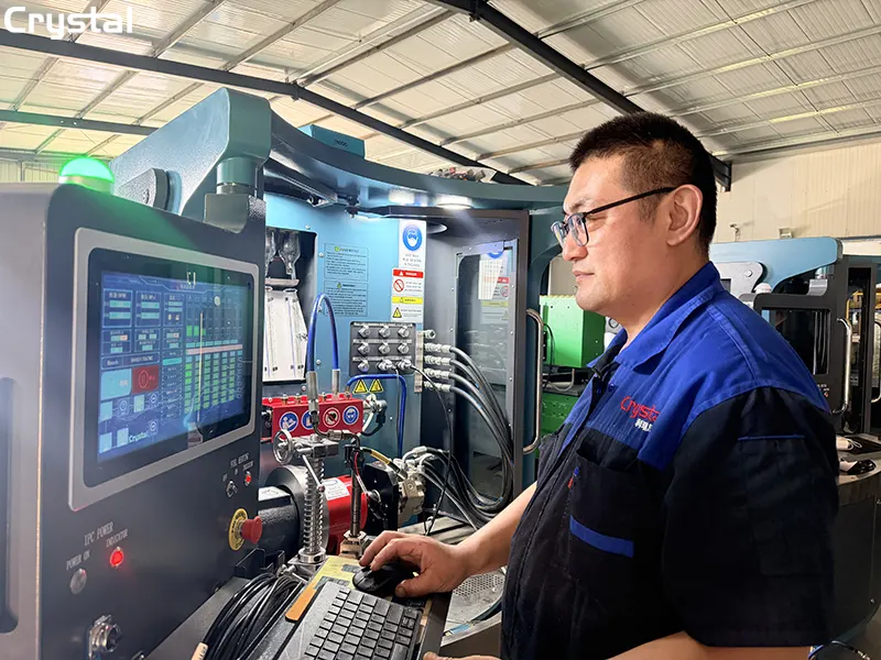
Crystal test benches feature comprehensive testing capabilities including solenoid valve response characteristic analysis and system sealing detection. The bench can test the DRV valve across its full operating range and compare the response curve against the OEM specification.
5. Start Pressure and Cranking Delivery Test
The start pressure test evaluates whether the pump can generate sufficient pressure to start the engine. This is a critical diagnostic because a pump that performs adequately at operating speed may fail to build enough pressure during cranking.
How the Test Works
The high-pressure pump must generate at least 150 to 200 bar of pressure at the start for the engine to run in the Common Rail System. The test bench simulates cranking conditions—low speed, cold fluid—and measures the pressure the pump can generate.
The test procedure involves:
- Setting the pump speed to cranking RPM (typically 200-300 RPM)
- Measuring the pressure generated within a specified time
- Comparing against the minimum start pressure specification
- Measuring the delivery volume during the cranking period
What the Results Reveal
If the pump cannot generate 150 bar during cranking, the engine will not start regardless of injector condition. This is a common cause of "crank-no-start" conditions on high-mileage diesel engines. A pump that barely reaches the threshold when cold will fail entirely in cold weather.
Common Failure Modes Detected
- Worn plunger-barrel assemblies that cannot seal at low speed
- Weak delivery valve springs
- Fuel control actuator stuck in low-delivery position
- Air ingress into the pumping chamber
Crystal Test Bench Advantage
Crystal test benches feature precise speed control from 0 to 4,000 RPM, allowing operators to simulate cranking conditions accurately. The system measures both pressure and delivery volume during the cranking test, providing a complete picture of pump starting capability.
6. Plunger and Barrel Condition Assessment
The plunger and barrel assembly is the heart of any high-pressure pump. It is also the component most susceptible to wear due to the extreme pressures and marginal lubrication conditions in common rail systems.
How the Test Works
Plunger condition is assessed through a combination of tests:
Flow consistency across pressure range: The pump's flow is measured at multiple pressure points. A healthy plunger maintains consistent delivery efficiency across the full pressure range. A worn plunger shows decreasing efficiency at higher pressures.
Pressure decay with delivery valve blocked: By isolating the plunger from the delivery valve, the test bench can determine whether leakage is occurring in the plunger-barrel assembly itself.
Cylinder-to-cylinder balance (multi-plunger pumps): For pumps with multiple plunger assemblies (such as the CP3 with its three plungers), the test bench measures delivery from each section individually. Variation exceeding 5% between cylinders indicates wear in one or more plunger assemblies.
What the Results Reveal
Research has shown that the highest difference in delivery between new and used pumps exists at the maximal compression pressure. This means that plunger wear manifests most clearly at high pressure—the very condition where the pump is most stressed.
If a plunger displays pressure below 300 bar, replacement is recommended. For the Bosch CP4 pump, the roller shoe follower design has proven to be far more sensitive to ultra-low sulfur diesel and low-lubricity fuel. When lubricity is insufficient, the follower can seize and skid on the cam instead of rolling, causing the pump to self-destruct.
Common Failure Modes Detected
- Plunger scuffing and seizure
- Barrel erosion from contaminated fuel
- Delivery valve seat damage
- Cam and roller wear (CP4/CP4.2 pumps)
Crystal Test Bench Advantage
Crystal test benches can test 4-cylinder common rail pumps (optional function) and measure high-pressure maintenance power for each section. The system evaluates plunger condition by comparing delivery efficiency across the full pressure range and identifying cylinders that deviate from specification.
Summary: The 6 Diagnostic Methods at a Glance
| Diagnostic Method | Primary Parameter | Failure Indicated | Typical Threshold |
| 1. Flow Efficiency | Delivery at multiple pressures | Plunger/valve wear | <60 ml/1000 strokes at max pressure |
| 2. Pressure Decay | Pressure drop rate when stopped | Internal leakage | >10% per minute |
| 3. Return Flow | Back leakage volume | Worn plungers, seals | >20% of total input |
| 4. DRV Valve Function | Pressure-current response | Valve sticking/leakage | Non-linear response |
| 5. Start Pressure | Cranking pressure | Low-speed sealing | <150 bar at cranking RPM |
| 6. Plunger Condition | Per-cylinder delivery balance | Plunger/barrel wear | >5% variation between cylinders |
The Crystal Automation Advantage
Crystal Automation's injection pump test benches—including the CRS1000 series and 12PSB series—are engineered to perform all six of these diagnostic methods with precision and efficiency.
The CRS1000 series features a modular design that allows the bench to be configured for testing high-pressure common rail injectors, high-pressure common rail pumps, EUI and EUP systems, HEUI systems, and medium-pressure actuating pumps. Users can select a single testing function or combine two or even three functions in one system, making it a cost-effective and future-ready testing platform.
Key diagnostic capabilities of Crystal test benches include:
- Comprehensive testing: Injector performance test, high-pressure oil pump test, common rail pipe and pressure sensor test, solenoid valve response characteristic analysis, and system sealing detection
- High-precision measurement: Flow measurement accuracy of 0.1 ml, with a flow testing range spanning 0–600 ml per 1,000 injections
- Advanced speed control: 0–4,000 RPM with frequency conversion technology
- Automated reporting: Built-in database with thousands of pump and injector profiles, automatic pass/fail assessment
- Durable construction: Test and waste oil tanks crafted from industrial-grade 304 stainless steel for maximum corrosion resistance, with a sophisticated three-stage filtration system to prevent contamination
The CRS1000 series delivers stable testing results and reliable long-term operation, helping users achieve accurate diagnostics and consistent performance every day.
Conclusion
Diagnosing high-pressure pump failures requires more than a single test—it demands a systematic, multi-method approach. The six diagnostic methods outlined here—flow efficiency testing, pressure decay analysis, return flow measurement, DRV valve function testing, start pressure verification, and plunger condition assessment—each reveal different aspects of pump health.
By combining these methods on a modern injection pump test bench, diesel workshops can:
- Identify the exact failure mode rather than guessing at the problem
- Quantify the severity of wear to determine whether repair or replacement is appropriate
- Verify repairs before returning the pump to service
- Document results for customer communication and quality assurance
With a Crystal Automation test bench and a disciplined diagnostic approach, your workshop can confidently diagnose and resolve high-pressure pump failures—reducing comebacks, increasing customer satisfaction, and maximizing the return on your equipment investment.
Written by
Taian Crystal Automation Co., Ltd.
Editor Chen
www.crystalautotest.com
WhatsApp:+86 185 9528 8526
Email:martin@crystalautotest.com
- Top 5 Must-Know Signs Your Injection Pump Test Bench Calibration Is Off
- From Diagnosis to Repair: How Crystal Common Rail Test Benches Reduce Diesel Engine Downtime
- Top 10 High Quality Fuel Injector Test Bench Reviews
- Two CR318Pro Common Rail Injector Test Bench Shipped Simultaneously to Italy - Made in China Earns Dual Recognition in the European Market

Crystal Automation is a leading Chinese manufacturer of common rail test benches and fuel injector test benches.