Top Common Rail Injector Test Bench Guide: Working Principle & 7 Key Testing Parameters
Modern diesel common rail systems have evolved from first-generation pressures of 1,350 bar to fourth-generation pressures of 2,500 bar, with 3,000 bar designs already under development. At these pressures, even the smallest deviation in an injector—a few milliliters of flow error, a few hundred microseconds of response delay—is enough to alter combustion quality inside the engine. The common rail injector test bench exists precisely to transform these "small deviations" from subjective judgment into quantifiable, repeatable technical data.
Understanding how a common rail injector test bench works, and what it actually measures, is the prerequisite for using the equipment correctly, interpreting data reliably, and making sound repair decisions. This guide covers two dimensions: the working principle and the 7 key testing parameters.
Part 1: How a Common Rail Injector Test Bench Works
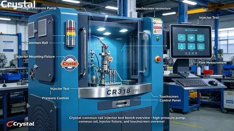
A common rail injector test bench is essentially a controlled diesel high-pressure environment simulator. It removes the mechanical constraints of the engine and places the fuel system under laboratory conditions, so that every performance indicator of the injector can be measured independently and precisely.
1. The Hydraulic Circuit: From Tank to Injector
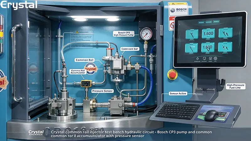
The hydraulic circuit of a common rail injector test bench closely mirrors the topology of an on-vehicle common rail system, but every stage is "taken over" by the test equipment.
High-pressure generation is the first stage. The test bench typically uses a high-pressure pump of the same specification as the on-vehicle system—for example, a Bosch CP3 series pump—driven by an electric motor to draw calibration fluid from the tank and pressurize it to the required rail pressure. The system configured on the Crystal CR918-PRO can generate pressures up to 2,600 bar, while some industrial-grade common rail injector test benches have a nominal pressure range of 0–2,800 bar.
The common rail acts as a hydraulic accumulator, stabilizing the pressure pulsations from the high-pressure pump. A rail pressure sensor monitors pressure in real time, and a pressure relief valve provides safety redundancy against overpressure.
The injector mounting fixture is the execution endpoint of the test. The injector under test is clamped in a dedicated fixture, the high-pressure fuel line connects to the inlet, the return line connects to the return flow measurement channel, and the electrical interface connects to the control unit. Every injection event of the injector occurs under the control of the common rail injector test bench.
The return flow and leakage measurement channel operates in parallel with the injection measurement. Some test benches use independent return backpressure regulation, so that the leakage flow measurement is not affected by fluctuations in injection backpressure—thereby quantifying "injection quantity" and "return quantity" as two independent physical quantities.
2. The Electronic Control Circuit: Drive Signals and Signal Feedback
Common rail injectors—whether solenoid-type or piezoelectric-type—require precise electrical signals to actuate. The electronic control circuit of a common rail injector test bench performs two tasks: on-demand drive and synchronous measurement.
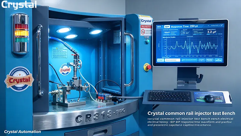
For solenoid injectors, the control unit outputs a drive signal with a specific pulse width and current waveform, causing the solenoid coil to generate a magnetic field that pulls the armature to open the needle valve. BIP (Beginning of Injection Pulse) detection technology uses the inductance discontinuity caused when the solenoid armature seats, extracting the actual needle valve opening moment from the "knee" in the current curve. The detection window for this method is typically around 600 μs wide, corresponding to sub-millisecond timing accuracy requirements.
For piezoelectric injectors, the drive logic is entirely different. Piezoelectric actuators are capacitive loads, and their actuation depends on charge control during charging and discharging. The common rail injector test bench must be able to measure the capacitance (typically in the microfarad range) and insulation status of the piezo element to judge the electrical health of the actuator. Capacitance measurement essentially reflects the geometric integrity and material state of the piezo ceramic stack—a piezo injector with a capacitance value outside specification cannot produce the correct needle valve lift, even if its appearance is intact.
3. The Software Layer: From Raw Signals to Verdicts
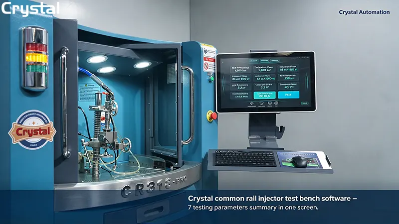
Signals collected by sensors—pressure, flow, temperature, current, voltage—enter the common rail injector test bench software through the data acquisition system. The core function of the software is not to "display numbers," but to map raw measurements into engineering verdicts.
The software of a modern common rail injector test bench has a built-in database of test specifications for thousands of injector models. Once the operator selects the injector model, the software automatically retrieves the corresponding test conditions (rail pressure, pulse width, temperature), nominal values, and tolerance bands. During testing, the software compares real-time measurements against the specification database, outputs "pass/fail" verdicts, and when necessary generates the calibration codes required by the ECU (IQA, IMA, ISA, QR, etc.). The Crystal CR918-PRO software system can automatically generate all major correction codes including QR, IQA, IMA, ISA, c2i, c3i, and ICC (VD0), eliminating dependence on external coding devices.
At this point, the hydraulic circuit provides "physical conditions," the electronic control circuit provides "actuation commands," and the software layer completes the "verdict loop." Together, these three constitute the complete working principle of a common rail injector test bench.
Part 2: The 7 Key Testing Parameters
The following 7 parameters are where a common rail injector test bench delivers its core value in diagnosis and calibration. Each parameter answers a specific question: "Is this injector still faithful to its design intent in this dimension?"
Parameter 1: Rail Pressure and Pressure Control Accuracy
The question it answers: Is the injector operating at the specified pressure?
Rail pressure is the reference for all other measurements. If a common rail injector test bench cannot hold the set pressure steady, the readings of flow, response time, and return flow lose their frame of reference. The pressure control accuracy of modern common rail test benches is typically in the order of ±0.1 MPa—for a working pressure of 2,600 bar, this is equivalent to less than 0.004% control error. The NTS300 has a nominal pressure range of 0–2,800 bar, the CR318C has a rail pressure upper limit of 2,700 bar, and the CRS1000 series has a pressure measurement range of up to 2,000 bar.
Pressure control accuracy is critical because the relationship between flow and pressure is nonlinear. A rail pressure deviation of 0.5 MPa at a working condition of 2,600 bar can introduce a flow measurement error of 0.5–1.0 ml per 1,000 injections—enough to push a qualified injector into the "fail" range, or vice versa.
Parameter 2: Injection Flow (Injection Quantity)
The question it answers: How much fuel did the injector actually deliver under specified conditions?
Injection flow is the highest-weighted parameter in common rail injector diagnostics. The common rail injector test bench measures the actual fuel volume delivered by the injector at the set rail pressure, pulse width, and injection count, using flow sensors or gravimetric systems. The flow measurement accuracy of modern test benches can reach the order of 0.1 ml, with a flow test range covering 0–600 ml per 1,000 injections; some equipment can reach a flow range of 0.008–4 L/min.
Flow data is not only the basis for "pass/fail" verdicts but also the input for calibration code generation. The ECU relies on the injector's flow characteristic codes to correct the actual injection quantity of each cylinder to achieve combustion balance. A common rail injector test bench that cannot measure flow accurately cannot generate valid correction codes—it will output a set of codes built on erroneous flow data, causing the engine to continue operating out of balance under the name of being "calibrated."
Parameter 3: Return Flow (Leakage)
The question it answers: How much fuel "escaped" from inside the injector without participating in injection?
Return flow measures the volume of fuel flowing out of the injector's return port. This parameter is often overlooked, but it reveals the health of the injector's internal seals and control chamber. An injector with return flow exceeding specification means fuel is leaking through worn needle guide surfaces, control plungers, or valve seats, rather than being directed to the nozzle to complete injection.
Modern common rail injector test benches typically measure return flow synchronously with injection measurement, ensuring both are collected under exactly the same pressure and temperature conditions. Some systems use independent return backpressure regulation, so that leakage flow measurement is not affected by fluctuations in injection backpressure. Abnormally elevated return flow is often an early signal of injector performance degradation—before injection flow has noticeably declined, return flow can already indicate the progress of internal wear.
Parameter 4: Response Time (BIP)
The question it answers: How long does the injector delay from the drive signal being issued to the needle valve actually actuating?
Response time (BIP time) is a direct measure of the timing accuracy of solenoid injectors. Its physical basis is that when the solenoid armature seats and the needle valve begins to move, the coil inductance changes abruptly, appearing as a detectable "knee" in the drive current curve. The time difference from the electrical signal being issued to the detection of this knee is the BIP time, typically recorded in microseconds (μs).
The significance of BIP time lies not in the absolute value itself, but in consistency and repeatability. The ECU's control strategy is built on the premise that injectors have a known, stable response time. An injector with drifting BIP time means a phase error has appeared between the injection command issued by the ECU and the moment fuel actually enters the cylinder—the interval between pilot and main injection may be compressed or stretched, affecting combustion noise, emissions, and fuel economy.
Parameter 5: Capacitance and Electrical Parameters (Piezoelectric Injectors)
The question it answers: Is the electrical state of the piezoelectric actuator healthy?
For piezoelectric injectors, capacitance measurement is the core of electrical diagnosis. The capacitance value of a piezo ceramic stack is directly related to its geometric dimensions, material dielectric constant, and internal integrity. A piezo injector with a capacitance value outside specification may mean delamination, cracks, or contamination between ceramic layers—even if its appearance and mechanical dimensions are completely normal.
The capacitance measurement of a common rail injector test bench typically covers the microfarad (μF) range, combined with resistance and insulation testing to form a complete assessment of the electrical state of the piezo actuator. The CR318C explicitly lists "piezoelectric injector resistance and capacitance testing" as a function, while the NTS300 supports "injector solenoid inductance and capacitance detection." The combination of capacitance, insulation, and response time reflects the true health of a piezo injector better than any single parameter alone.
Parameter 6: Test Fluid Temperature
The question it answers: Are the measurement conditions controlled?
Test fluid temperature is a "background parameter," but its influence on the first five parameters is systemic. The viscosity of diesel changes with temperature, and viscosity directly determines the flow through the nozzle and internal clearances. ISO 4113 standard calibration fluid has a kinematic viscosity strictly specified as 2.74 ± 0.04 mm²/s at 40°C, and SAE J967 also requires test fluid temperature to be controlled at 40°C.
A deviation of a few degrees in temperature causes viscosity to deviate from specification, and flow readings drift accordingly. This drift is systemic—it affects both injection flow and return flow simultaneously, making "pass/fail" verdicts rest on an incorrect thermodynamic basis. The intelligent temperature control system configured on a common rail injector test bench (such as the automatic oil temperature regulation on the CR318C) exists to lock this variable within a controllable range, so that measurements of other parameters are comparable.
Parameter 7: Calibration Code Generation
The question it answers: Can the repaired injector "communicate" with the ECU?
Calibration codes are not "measured"—they are calculated from measurement results. After the common rail injector test bench completes acquisition of flow, return flow, response time, and other parameters, the software converts these data into correction codes that the ECU can recognize—IQA, IMA, ISA, QR, c2i, c3i, ICC, etc. Each code corresponds to the ECU's correction strategy for a certain dimension of injector characteristics.
The NTS300 software supports Bosch IQA/IMA/ISA, Denso QR series, Delphi C2I/C3I, and Siemens IIC code generation, while the CR918-PRO covers QR, IQA, IMA, ISA, c2i, c3i, and ICC (VD0). The accuracy of code generation depends entirely on the measurement accuracy of the first six parameters. A common rail injector test bench with a flow measurement deviation of 0.3 ml will generate codes that guide the ECU to make incorrect corrections—the injector "passes" the test at the data level, but remains non-compliant at the engine level.
Part 3: How Crystal Test Benches Implement These Principles
The working principle and parameter system described above are concretely engineered in Crystal Automation's CR918-PRO and CRS1000 series.
The hydraulic system of the CR918-PRO is based on the Bosch CP3 high-pressure pump, capable of generating 2,600 bar rail pressure, paired with high-precision flow sensors to achieve 0.1 ml-level flow measurement. The electronic control system supports both solenoid and piezoelectric injectors, with BIP response time measurement covering microsecond-level timing and capacitance measurement for electrical diagnosis of piezo actuators. The software layer automatically executes the complete test sequence from idle injection, pilot injection, and full-load injection to return flow and leakage, and automatically generates all major correction codes upon completion of measurement.
The CRS1000 series, with its modular design, covers an even broader range of component types—common rail injectors, high-pressure pumps, EUI/EUP, HEUI—completing the full closed loop from hydraulic measurement to electronic control diagnosis on a single platform. The 304 stainless steel fuel circuit and three-stage filtration system ensure that the test fluid remains clean during long-term high-pressure cycling, so that the accuracy of temperature control and flow measurement does not decay due to contamination.
The Crystal Common Rail Injector Test Bench Advantage
Crystal Automation's common rail injector test benches are engineered to deliver every parameter described in this guide with precision and reliability:
- 2,600 bar pressure capability with ±0.1 MPa accuracy
- 0.1 ml flow measurement accuracy with a range of 0–600 ml per 1,000 injections
- BIP response time measurement with 0–999 μS resolution
- Piezoelectric capacitance testing covering 0–12 μF
- Temperature control at 40 ± 2°C as standard
- Automatic calibration code generation (QR, IQA, IMA, ISA, c2i, c3i, ICC)
- 304 stainless steel fuel circuits with three-stage 10-micron filtration
- Fully automatic multi-injector testing—4 injectors in under 15 minutes
Every Crystal common rail injector test bench is factory-calibrated and shipped with a comprehensive calibration certificate, ensuring that customers receive equipment ready for immediate, accurate use.
Part 4: From Principle to Practice—The Logic of the Parameter System
The value of understanding the working principle and testing parameters ultimately manifests in the logic of use: pressure is the reference, flow and return flow are the core verdicts, response time and capacitance reveal electrical health, temperature locks the measurement conditions, and coding converts measurements into executable repair outputs.
If a common rail injector test bench can only output "pass/fail" without providing parameter-level trend data, its diagnostic value is limited to binary judgment. Truly experienced repair decisions require seeing the small drift of flow between repeated tests, the gradual rise of return flow relative to historical baseline, and the comparative change of BIP time before and after repair. This information only emerges when the parameter system is completely and accurately measured and recorded.
The working principle of a common rail injector test bench is not mysterious—it is a controlled pressure environment, a set of precise drive and measurement circuits, and a software layer that maps signals to verdicts. Its technical depth lies in whether each parameter is measured accurately enough, and whether these parameters are combined into a diagnostic picture that can guide action. Seven parameters answer seven different questions; together, they answer the same question: can this injector be safely installed back into the engine?
Conclusion
A common rail injector test bench is the bridge between diesel diagnostics and reliable repair. It transforms the invisible behavior of fuel injectors into measurable, repeatable data—pressure, flow, return flow, response time, capacitance, temperature, and calibration codes.
Understanding how a common rail injector test bench works, and what each of its 7 key testing parameters reveals, is the foundation of professional diesel service. Whether you are evaluating equipment for purchase, diagnosing a stubborn injector fault, or training new technicians, this parameter system provides the framework for confident, data-driven decisions.
For workshops that demand precision, Crystal Automation's common rail injector test benches—including the CR918-PRO and CRS1000 series—deliver the pressure accuracy, flow precision, and automated calibration code generation that modern diesel diagnostics require.
Written by
Taian Crystal Automation Co., Ltd.
Editor Chen
www.crystalautotest.com
WhatsApp:+86 185 9528 8526
Email:martin@crystalautotest.com
- Top 7 Injection Pump Test Bench Calibration Best Practices from Crystal Engineers
- Multi-functional Common Rail Test Bench vs Single-Function Unit: Cost & Performance Analysis by Crystal Automation
- Top 7 Factors to Choose a Reliable Common Rail Injector Test Bench for Diesel Repair Shops
- Top 8 Differences: Injection Pump Test Bench vs Common Rail Test Bench

Crystal Automation is a leading Chinese manufacturer of common rail test benches and fuel injector test benches.