Injection Pump Test Bench Setup: 6 Essential Steps Before Your First Test Run
A fuel injection pump test bench is one of the most important investments a diesel workshop can make. But owning the equipment is only half the battle—proper setup is what separates accurate, repeatable test results from wasted time and misdiagnosed pumps.
Whether you're setting up a new Crystal 12PSB series injection pump test bench or commissioning a refurbished unit, following a systematic setup procedure is essential. The 12PSB series adopts advanced frequency conversion speed regulation technology, offering precise control and energy efficiency—but even the best technology demands correct installation and configuration.
Here are 6 essential steps to set up your injection pump test bench before running your first test.
1. Proper Mounting and Alignment of the Test Pump
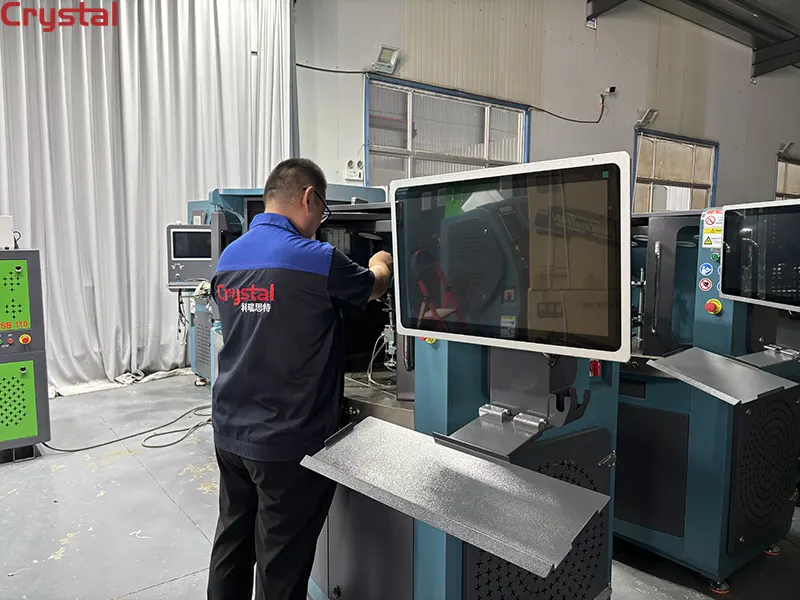
The foundation of accurate testing begins with correct physical installation. The high-pressure pump must be securely mounted and precisely aligned with the test bench's drive shaft.
The procedure:
- Fix the high-pressure pump on the guide rail of the workbench using a special clamping device
- Connect the front end of the high-pressure pump to the universal joint of the test bench through a coupling
- Ensure the camshaft of the high-pressure pump is coaxial with the drive shaft of the test bench—this can be achieved by installing a special pad between the pump and the guide rail
- After initial fixation, turn the dial of the universal joint for 1 to 2 turns
- When rotation feels smooth, tighten the large bolts and nuts securely
What to check: After installation, the high-pressure pump should run smoothly and freely, be solid and reliable, and have no vibration or looseness. Even a slight misalignment can cause premature wear on the drive coupling and affect test accuracy.
Crystal Advantage: Crystal test benches feature precision-machined mounting beds and universal joints designed for quick, accurate pump alignment. The 12PSB series offers flexible clamping options for various pump types, reducing setup time and minimizing alignment errors.
2. Electrical Connections and Power Supply Verification
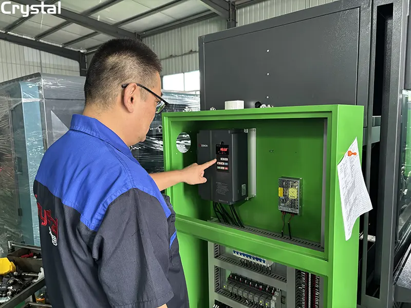
Before applying power, verify all electrical connections are correct and secure.
Power requirements:
- Supply voltage: 220VAC or 380VAC (three-phase)
- Frequency: 50Hz or 60Hz
- Motor power options: 7.5kW, 11kW, 15kW, 18.5kW, or 22kW
Startup procedure:
- Connect the three-phase power supply to the test bench
- Turn the speed control handle to zero position
- Press the motor start button (green)—the motor will start
Shutdown procedure (critical safety step):
- When stopping, turn the speed control handle to reduce the dial speed to zero first
- Then press the stop button (red)
- Never stop at high speed—this can damage the test bench and cause accidents when starting next time
Crystal Advantage: Crystal test benches are equipped with comprehensive electrical protection systems, including overload protection and emergency stop functionality. The intuitive control panel makes startup and shutdown straightforward, reducing the risk of operator error.
3. Calibration Fluid Selection and Temperature Control
The choice and condition of calibration fluid directly impact test accuracy. SAE J967 calibrating fluid is the industry standard.
Fluid specifications:
- Calibrating fluid must conform to SAE J967 standards
- Fuel must be light diesel oil that has been precipitated for more than 48 hours
- The fluid should maintain a temperature of 110°F–115°F (43°C–46°C) at the pump inlet over all speed and load ranges
- Test oil temperature for Bosch calibration procedures: 40°C
Temperature control procedure:
- When fuel temperature is below 40°C, turn the heating valve handle clockwise to increase fuel temperature
- When fuel temperature reaches 40°C, immediately close the heating valve to stop heating
Why it matters: Fuel viscosity changes with temperature. A deviation of just a few degrees can introduce flow measurement errors of 5% or more. Proper temperature control is non-negotiable for accurate calibration.
Crystal Advantage: Crystal injection pump test benches feature integrated temperature control systems with digital displays, allowing operators to monitor and maintain calibration fluid temperature precisely within the required 110°F–115°F range.
4. System Priming, Bleeding, and Warm-Up
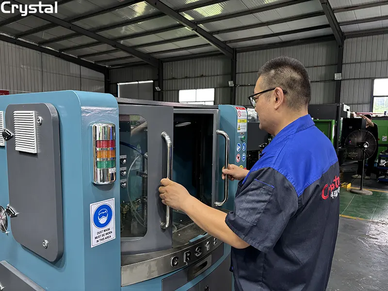
Air in the fuel system is the enemy of accurate testing. Before taking any measurements, the system must be properly primed and bled.
Priming procedure:
- Install high-pressure injection lines using new copper gaskets
- Leave fuel line connections at the pump and nozzles loose initially—this allows air to escape
- Apply power and operate the pump at 2000 rpm wide-open throttle (WOT) for 10 minutes to bring to operating temperature and clear air from the system
- After air is cleared, tighten all connections securely
- Check connections for leaks while operating
The run-in requirement:
- Run a minimum of 250 strokes before taking any calibration measurements
- Run 500 strokes when fuel delivery is less than 75 cc
- This allows pump components to settle and the calibration fluid to reach stable temperature
Critical note: Fuel must be delivered to the injection pump air-free (without bubbles) and at a pressure of 0.3 to 0.5 bar gauge pressure. A suitable pressure monitoring system should be installed in the injection pump feed line.
Crystal Advantage: Crystal test benches feature integrated priming and bleeding systems that simplify the air-removal process. The digital pressure display allows real-time monitoring of fuel supply pressure, ensuring air-free delivery at the correct 0.3–0.5 bar.
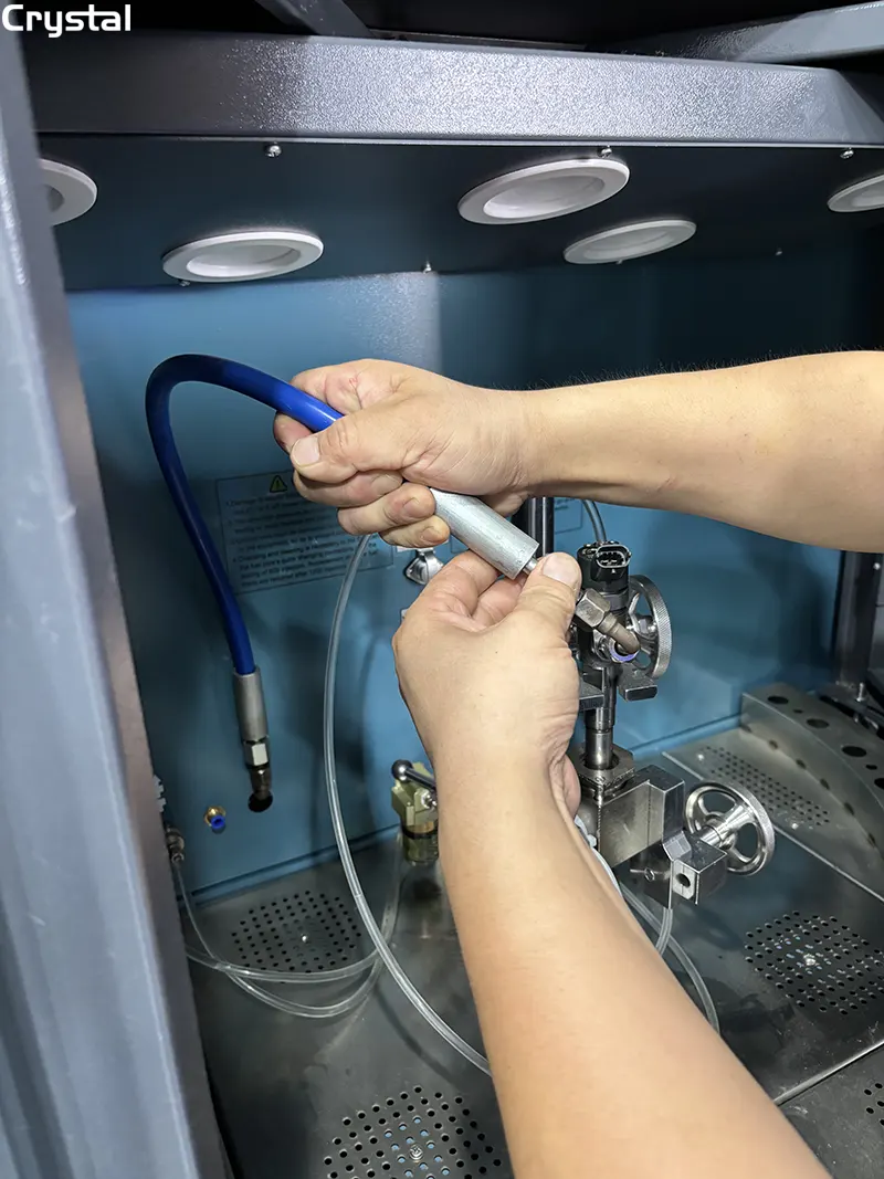
5. Speed and Pressure Parameter Configuration
With the system primed and warm, configure the test parameters according to the pump manufacturer's specifications.
Speed control:
- Adjustable rotation speed range: 0–4,000 RPM
- Select the appropriate gearbox gear for the required speed and direction
- Turn the speed control handle to change speed—the larger the deflection horizontal angle, the higher the speed
- Injection pump operating speed is typically half of engine speed
Pressure regulation:
- The pressure in the fuel system is regulated with a pressure regulating valve
- Turning the handwheel clockwise: pressure adjustable in the range of 0–0.6 MPa
- Turning the handwheel counterclockwise: pressure adjustable in the range of 0–6 MPa
- Pressure oil is sent from the oil supply joint to the high-pressure pump under test through the oil pipe
Standard test equipment requirements:
- Injector lines must be 0.093 in. (2.36 mm) inside diameter and 25 in. (63.5 cm) long
- Test stand injector nozzles must include a 0.020 in. (0.5 mm) orifice plate
- Calibrating nozzles should be set at 1700 ± 25 psi (11,721 ± 172 kPa)
Crystal Advantage: Crystal 12PSB series test benches feature advanced frequency conversion speed regulation technology, providing precise speed control across the full 0–4,000 RPM range. The digital control interface allows operators to set and store test parameters for different pump types, reducing setup time for repeat tests.
6. Pre-Test Verification and Final Checks
Before running your first actual test, perform these verification checks to ensure everything is functioning correctly.
Standard injector verification:
- Check the opening pressure of the standard fuel injector—it should be 17.5 MPa
- Regularly check the uniformity of the standard fuel injector
- If there is any difference, adjust the opening pressure to correct calibration
- If adjustment is not possible, replace the standard injector
Rotation direction:
Rotation of the fuel injection pump camshaft for bench testing should be counterclockwise as seen from the drive end of the fuel injection pump
Final checks:
- Verify all connections are tight and leak-free
- Check that the fuel rack end is within 0.005 inch of the specified setting
- Confirm calibration fluid temperature is stable at 110°F–115°F
- Ensure the pump has completed the minimum 250-stroke run-in period
- Verify the pressure monitoring system shows 0.3–0.5 bar at the pump inlet
Fluid maintenance reminder:
- When debugging 500 fuel injection pumps or after 400 hours of operation, new oil should be replaced
- When changing oil, clean the fuel tank and filter with kerosene
- 30# or 46# steam turbine oil should be added to the gearbox and hydraulic system
Crystal Advantage: Crystal test benches are built with durability in mind. The 12PSB series features high-quality frequency conversion devices with characteristics including high reliability, ultra-low noise, energy saving, high output torque, and perfect auto-protecting functions. Each machine comes with a detailed manual and training video, ensuring your team can get up to speed quickly and maintain the equipment properly.
Summary: The 6-Step Setup Process
| Step | Action | Key Specification |
| 1 | Mount and align test pump | Coaxial alignment, smooth rotation (1–2 turns) |
| 2 | Electrical connections | 380V three-phase, 7.5–22kW motor power |
| 3 | Calibration fluid | SAE J967, 110°F–115°F (43°C–46°C) |
| 4 | Prime, bleed, and warm-up | 2000 rpm for 10 minutes, 250-stroke minimum run-in |
| 5 | Speed and pressure settings | 0–4,000 RPM, 0–6 MPa pressure range |
| 6 | Pre-test verification | 17.5 MPa standard injector, 0.005 inch fuel rack tolerance |
Common Setup Errors to Avoid
| Error | Consequence | Prevention |
| Misaligned pump mounting | Premature coupling wear, inaccurate readings | Always verify coaxial alignment |
| Starting at high speed | Equipment damage, safety hazard | Always start from zero speed |
| Testing before warm-up | 5%+ flow errors | Always reach 110°F–115°F first |
| Air in fuel system | Erratic delivery readings | Always prime and bleed thoroughly |
| Skipping run-in period | Artificially low delivery | Always run 250+ strokes before measuring |
| Incorrect rotation direction | Pump damage | Verify counterclockwise rotation |
Conclusion
Proper setup of your injection pump test bench is not optional—it's essential for accurate, repeatable test results. These 6 essential steps—from correct mounting and electrical connections through fluid temperature control, system priming, parameter configuration, and pre-test verification—ensure that every pump leaving your bench meets OEM specifications.
With a Crystal 12PSB series injection pump test bench, you're investing in precision engineering, advanced frequency conversion technology, and reliable performance. But even the best equipment requires proper setup. Take the time to follow these steps, and your test bench will deliver years of accurate, dependable service.
The result: fewer comebacks, more satisfied customers, and a reputation for quality that sets your workshop apart.
Written by
Taian Crystal Automation Co., Ltd.
Editor Chen
www.crystalautotest.com
WhatsApp:+86 185 9528 8526
Email:martin@crystalautotest.com
- Silk Road Bonds, Synchronized Progress - Kazakh and Serbian Customers Visit on the Same Day, Both Sign Contracts for CR818 Comprehensive Test Rig
- HCR708 Comprehensive Test Bench Enters South African Market---Injecting New Momentum into Africa Diesel Repair Industry
- HCR918 Multi-functional Common Rail Test Bench Goes Operational in Ecuador
- Mexican Client Orders CR318Pro Test Bench-Made in China Boosts the Upgrading of Latin America's Diesel Repair Industry

Crystal Automation is a leading Chinese manufacturer of common rail test benches and fuel injector test benches.