Injection Pump Test Bench Flow Accuracy: 7 Calibration Steps to Avoid Costly Errors
A fuel injection pump is the heart of any diesel engine. It must deliver an equal amount of fuel to each engine cylinder at the correct time. When flow accuracy drifts, the consequences are immediate and expensive: rough idling, black smoke, reduced power, increased fuel consumption, and ultimately, catastrophic engine failure.
Yet many workshops treat test bench calibration as an afterthought—something to do "when we have time." This approach is a recipe for costly errors.
Industry standards demand that variation between pumping elements should not exceed 3 percent at full load speed and 12 percent at low idle. On a used pump, it is permissible to go slightly above 12 percent on low idle. But even these tolerances are tight—and without proper calibration, your test bench won't detect when a pump falls outside them.
Here are 7 calibration steps to ensure your injection pump test bench delivers the flow accuracy your workshop—and your customers—depend on.
Step 1: Verify Test Stand Equipment and Setup
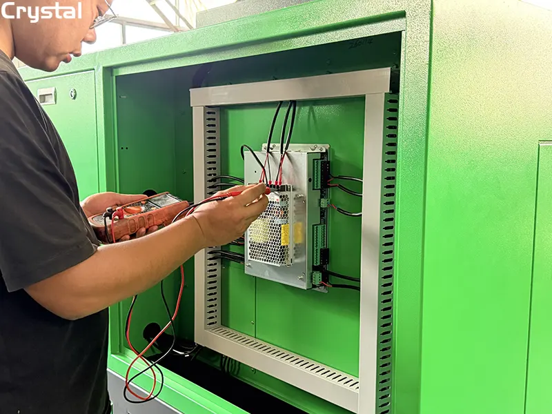
Before any calibration begins, ensure your test stand meets the minimum equipment requirements. Many calibration errors originate not from the pump itself, but from inadequate or poorly maintained test equipment.
Essential test stand requirements:
- Self-aligning zero-backlash drive coupling – eliminates rotational play that skews timing measurements
- Digital tachometer – provides precise RPM readings; the test bench must be capable of at least 2,250 rpm shaft speed
- Adjustable DC voltage source – used to check operation of cold advance and shutoff solenoids
- Transfer pressure gauge – operating range 0–160 psi (0–1103 kPa), calibrated in 1 psi increments
- Housing pressure gauge – operating range 0–30 psi (0–207 kPa)
- Fuel flowmeter – for precise delivery measurement
Test injector requirements:
- Injector lines must be 0.093 in. (2.36 mm) inside diameter and 25 in. (63.5 cm) long
- Test stand injector nozzles must include a 0.020 in. (0.5 mm) orifice plate
- Calibrating nozzle and holder assemblies must conform to SAE J968 specifications—available in single hole orifice plate and delay pintle type nozzle configurations
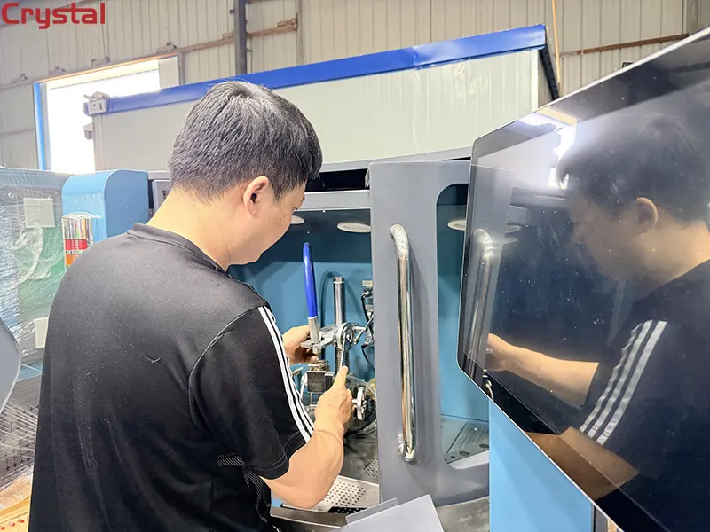
Why this matters: A worn or improperly sized nozzle will produce inaccurate flow readings regardless of how well the pump is calibrated. As one manual notes, "Nozzles in test stand must be in perfect condition at all times or the pump cannot be calibrated properly" .
Step 2: Control Calibration Fluid Temperature
Temperature is one of the most overlooked—yet most critical—variables in flow accuracy. Fuel viscosity changes with temperature, and viscosity directly affects flow rate through precision orifices.
Temperature specifications:
- Calibration fluid temperature must be checked as close to the transfer pump inlet as possible
- Operating temperature should be 110°F–115°F (43.3°C–46.1°C)
- If the test stand is in a cold room, run the pump until the calibrating oil is warmed up before taking measurements
Common error: Taking flow measurements before the calibration fluid has reached operating temperature. This can introduce errors of 5% or more in flow readings.
How to avoid it: Run the test stand with the pump at full load position (875 rpm) for several minutes until all air is out of the system and the calibrating oil has reached temperature.
Step 3: Set Correct Fuel Supply Pressure
Fuel supply pressure to the injection pump must be precisely controlled. Too low, and the pump may starve; too high, and internal leakage increases.
Pressure specifications:
- Fuel supply pressure to fuel injector pump must be set at 4.5–5.5 psi (31–38 kPa)
- Transfer pump fuel pressure should be approximately 15 psi for most calibration procedures
Why this matters: Supply pressure directly affects the volume of fuel available to the pumping elements. A deviation of just 1 psi can change flow readings by 1–2%—enough to push a borderline pump outside acceptable tolerances.
Step 4: Perform the Minimum 250-Stroke Run-In
One of the most common calibration errors is taking measurements too early—before the pump and test stand have stabilized.
The procedure:
- Run a minimum of 250 strokes before taking any calibration measurements
- Run 500 strokes whenever fuel delivery is less than 75 cc
- This allows the pump components to settle, air to purge from the system, and the calibration fluid to reach stable temperature
Why this matters: A pump that hasn't been run-in will produce artificially low or inconsistent flow readings. Components need time to seat, and trapped air in the system will cause erratic delivery.
Step 5: Measure and Record Flow for Each Cylinder
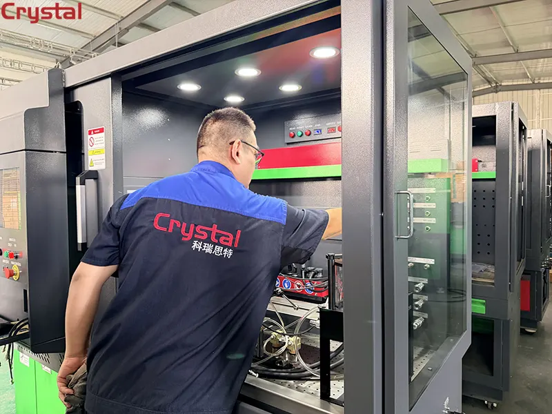
With the pump stabilized, it's time to measure fuel delivery for each cylinder. This is where flow accuracy is truly tested.
The procedure:
- Run the test stand with the pump at full load position (875 rpm)
- For each cylinder, collect and measure the fuel delivery volume
- Record the number of strokes—typically 500 strokes per measurement
- Check and record the fuel flow of each cylinder
Acceptable variation:
- At full load speed: variation between cylinders should not exceed 3 percent
- At low idle: variation should not exceed 12 percent
Data reference point: A typical delivery specification might read: 910 rpm, 82–84.0 cc per 500 strokes, 3.2 inches fuel rack setting.
Common error: Failing to measure all cylinders under identical conditions. Ensure the fuel rack setting, speed, and stroke count are identical for each measurement.
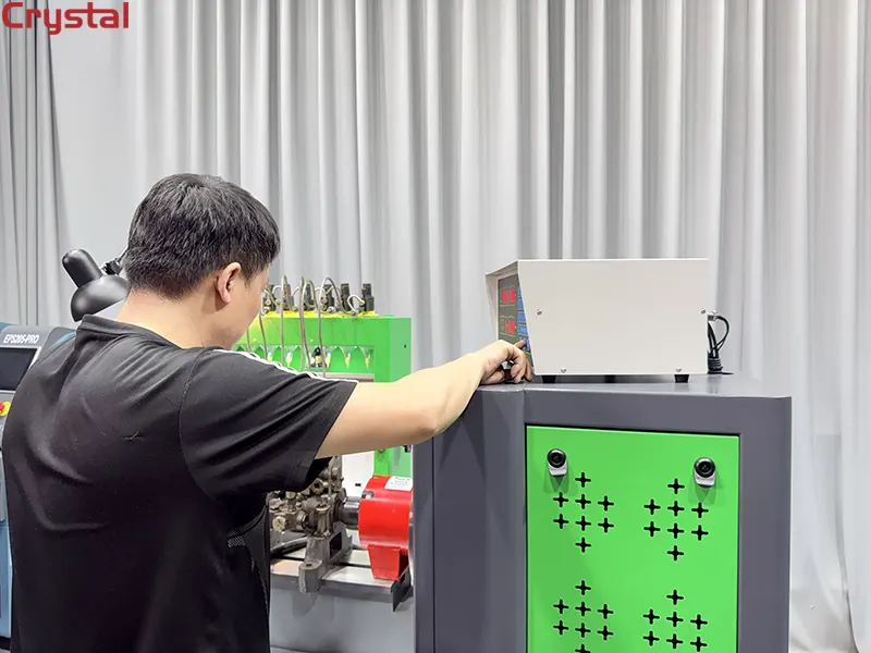
Step 6: Isolate Nozzle vs. Pump Variation
When you find excessive variation between cylinders, the next step is determining whether the problem lies in the pump or the nozzles.
The diagnostic procedure:
- If fuel draw shows considerable variation, remove the nozzles
- Switch the high and low nozzles to different cylinders
- Rerun the test
Interpreting results:
- If the variation follows the nozzles (the same cylinder now reads differently with a different nozzle), the nozzle is the problem—repair or recalibrate the nozzle assembly
- If the variation stays with the cylinder (the same cylinder still reads high or low regardless of which nozzle is installed), the problem is in the pumping element—repair or recalibrate the pump
Why this matters: Misdiagnosing a nozzle problem as a pump problem—or vice versa—wastes time and money. This simple swap test saves hours of unnecessary disassembly.
Step 7: Adjust and Verify Within Specified Limits
Once you've identified the source of variation, make adjustments and verify that all cylinders fall within acceptable tolerances.
Adjustment procedure:
- Loosen the gear segment clamping screws
- Hold the gear segment with a screwdriver and adjust the sleeve with a close-fitting pin
- Turn the sleeve to the right to increase fuel flow
- Turn the sleeve in the opposite direction to decrease fuel flow
Verification:
- Make adjustments as necessary to bring the variation within the specified limits
- After adjustment, rerun the full test sequence to verify all cylinders are within tolerance
- The fuel rack end must be within 0.005 inch of the specified setting
Final check: Variation percentage is calculated by taking the difference between the highest and lowest cylinder delivery. If all cylinders fall within the 3% (full load) and 12% (low idle) limits, the calibration is complete.
Summary: The 7-Step Calibration Process
| Step | Action | Key Specification |
| 1 | Verify test stand equipment | Zero-backlash coupling, digital tachometer, 0.020 in. nozzles |
| 2 | Control fluid temperature | 110°F–115°F (43.3°C–46.1°C) |
| 3 | Set supply pressure | 4.5–5.5 psi (31–38 kPa) |
| 4 | Run minimum 250 strokes | 500 strokes if delivery < 75 cc |
| 5 | Measure flow per cylinder | 3% max variation at full load, 12% at low idle |
| 6 | Isolate nozzle vs. pump | Swap high/low nozzles to identify source |
| 7 | Adjust and verify | 0.005 inch fuel rack tolerance |
Common Calibration Errors to Avoid
| Error | Consequence | Prevention |
| Taking measurements before warm-up | 5%+ flow error | Always reach 110°F–115°F first |
| Using worn or damaged nozzles | Inconsistent readings | Replace nozzles regularly; inspect 0.020 in. orifice plates |
| Skipping the run-in period | Artificially low delivery | Always run 250+ strokes before measuring |
| Ignoring supply pressure | Starvation or internal leakage | Verify 4.5–5.5 psi at transfer pump inlet |
| Not isolating nozzle vs. pump | Misdiagnosis and wasted time | Always swap high/low nozzles to identify source |
| Failing to verify after adjustment | Pump leaves shop out of spec | Rerun full test sequence after every adjustment |
The Crystal Automation Advantage
Crystal Automation's injection pump test benches are engineered to deliver the precision these calibration steps demand. With high-precision flow sensors, automatic measurement of oil quantity, and automatic generation of fuel pump maintenance reports, Crystal test benches reduce the risk of human error and ensure consistent, repeatable results.
Key features that support accurate calibration:
- Automatic calibration – when testing, the bench can automatically adjust parameters, collect and save data, and generate standard data for repair
- High-precision flow sensors – deliver the measurement accuracy needed to detect even small variations between cylinders
- Digital displays – real-time pressure monitoring improves calibration accuracy compared to analog gauges
Conclusion
Flow accuracy on an injection pump test bench is not optional—it's essential. A variation of just 3% at full load or 12% at low idle can mean the difference between a pump that delivers smooth, efficient power and one that causes rough running, black smoke, and premature engine failure.
By following these 7 calibration steps—and avoiding the common errors that plague many workshops—you can ensure that every pump leaving your bench meets OEM specifications. The result: fewer comebacks, more satisfied customers, and a reputation for quality that sets your workshop apart.
Written by
Taian Crystal Automation Co., Ltd.
Editor Chen
www.crystalautotest.com
WhatsApp:+86 185 9528 8526
Email:martin@crystalautotest.com
- Common Rail Test Bench Calibration: Why Precision Matters for Pump and Injector Diagnostics
- The 8 Most Common Faults in Common Rail Injector Test Benches
- Silk Road Bonds, Synchronized Progress - Kazakh and Serbian Customers Visit on the Same Day, Both Sign Contracts for CR818 Comprehensive Test Rig
- HCR918 Multi-functional Common Rail Test Bench Goes Operational in Ecuador

Crystal Automation is a leading Chinese manufacturer of common rail test benches and fuel injector test benches.