7 Steps to Accurately Test Piezoelectric Injectors at 2,600 Bar on a Common Rail Test Bench
Piezoelectric injectors represent the cutting edge of common rail diesel technology. Unlike traditional solenoid injectors, which rely on electromagnetic coils, piezoelectric injectors use ceramic actuators that expand when electrically charged—responding in microseconds rather than milliseconds. This faster response enables multiple injection events per combustion cycle, delivering better fuel economy, lower emissions, and smoother engine operation.
However, this precision comes at a cost. Piezoelectric injectors are complex, expensive components that require dedicated diagnostic equipment to test accurately. A high-quality common rail test bench—capable of generating pressures up to 2,600 bar (260 MPa) with ±0.1 MPa pressure control accuracy—is essential for proper diagnosis.
Here are the 7 essential steps to accurately test piezoelectric injectors on a common rail test bench.
Step 1: Proper Mounting and Preparation
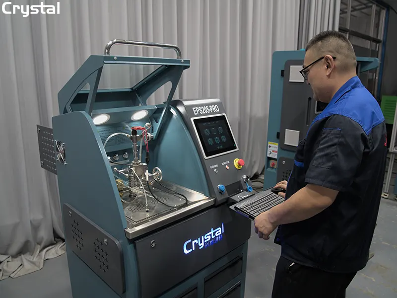
The testing process begins with correct injector mounting. The injector must be placed vertically in the test bench's fixture to prevent damage to its electrical components.
Key considerations:
- Use the appropriate brand-specific adapter for the injector being tested (Bosch, Denso, Delphi, Siemens, etc.)
- Ensure all sealing surfaces are clean and free of debris
- Lubricate the piezoelectric actuator before energizing—operating a piezo injector dry can cause permanent damage
- Connect the electrical harness with correct polarity
Data point: Crystal test benches support injectors from Bosch, Denso, Delphi, Siemens, Caterpillar, and Cummins, with built-in databases containing over 4,000 injector data profiles.
Step 2: Electrical Verification – Capacitance, Resistance, and Insulation
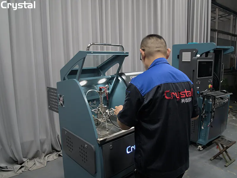
Before any hydraulic testing begins, the test bench performs a comprehensive electrical verification. This step is critical because electrical faults can mimic mechanical failures—and piezoelectric injectors are particularly sensitive to electrical issues.
Tests performed:
- Capacitance measurement – typical range: 0 – 12 μF
- Resistance measurement – checks the integrity of the piezo stack
- Insulation integrity test – detects short circuits or leakage paths
- Piezo element stroke and gap measurement
Why this matters: The Mega Tester V4, a specialized piezoelectric diagnostic system, is designed specifically to measure these parameters—capacitance, resistance, insulation integrity, piezo element stroke, and gap. A test bench with integrated electrical diagnostics eliminates the need for separate testing equipment.
Step 3: High-Pressure System Build-Up and Sealing Test
With electrical verification complete, the test bench builds hydraulic pressure to simulate real-world operating conditions.
Pressure parameters:
- Maximum test pressure: up to 2,600 bar (260 MPa)
- Pressure control accuracy: ±0.1 MPa (1 bar)
- Working oil temperature: must not exceed 42°C during extended operation
Sealing test procedure:
- Pressurize the injector to the specified test pressure
- Stop the pump and allow pressure to drop gradually
- Measure the pressure decay rate—excessive decay indicates internal leakage
- Compare against OEM specifications
Data point: A leaking injector with excessive return flow can cause the engine to run rough, lose power, or fail to start entirely. The sealing test catches these issues before they cause catastrophic engine damage.
Step 4: Minimum Pressure and Chatter Test
The chatter test determines the minimum pressure at which the injector needle begins to move—a critical indicator of injector health.
Test procedure:
- Activate the automatic triggering cycle
- Gradually reduce rail pressure while monitoring injector response
- Identify the minimum pressure that allows the chatter (needle movement)
- Record and compare against OEM specifications
What this reveals:
- Low minimum pressure – may indicate worn components or weak spring tension
- High minimum pressure – suggests sticking needle, contamination, or mechanical binding
Step 5: Return Flow (Back Leakage) Measurement
Return flow measurement is often overlooked but provides critical insight into internal injector wear.
Test procedure:
- Pressurize the injector to operating pressure
- Collect and measure the fuel returning through the leak-off port
- Compare against acceptable leakage time values
What excessive return flow indicates:
- Worn needle and guide surfaces
- Damaged sealing surfaces
- Internal component degradation
Data point: An injector with excessive return flow has "extra internal leakage"—fuel that bypasses the intended hydraulic circuit, reducing injection pressure and delaying injection timing. This leads to reduced engine power and, in severe cases, engine shutdown.
Step 6: Flow Rate Measurement and Injection Timing
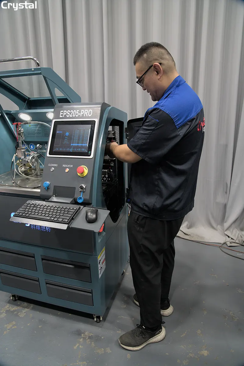
Flow rate is the single most critical diagnostic parameter for any injector. The test bench measures fuel delivery volume across multiple operating conditions.
Test parameters:
- Injection duration range: 100 – 5,000 μs (microseconds)
- Flow measurement accuracy: 0.1 ml
- Injection timing: measured from electrical command to mechanical movement
Standard test points:
- Idle fuel injection volume
- Pre-injection volume
- Full-load fuel injection volume
- Fuel injection volume at discharge point
Why injection timing matters: "Injection time is the time elapsed between the opening and closing of the nozzle. It is essential to determine the flow". An injector that responds with a delay—or one that fails to close completely—will deliver incorrect fuel quantities, affecting engine performance and emissions.
Data point: Piezoelectric injectors have a shorter injection delay than solenoid injectors, whether new or fouled. This faster response is precisely why they enable multiple injection events per cycle—but it also means timing tolerances are tighter and require more precise measurement.
Step 7: Report Generation and Calibration Coding
The final step transforms raw test data into actionable intelligence.
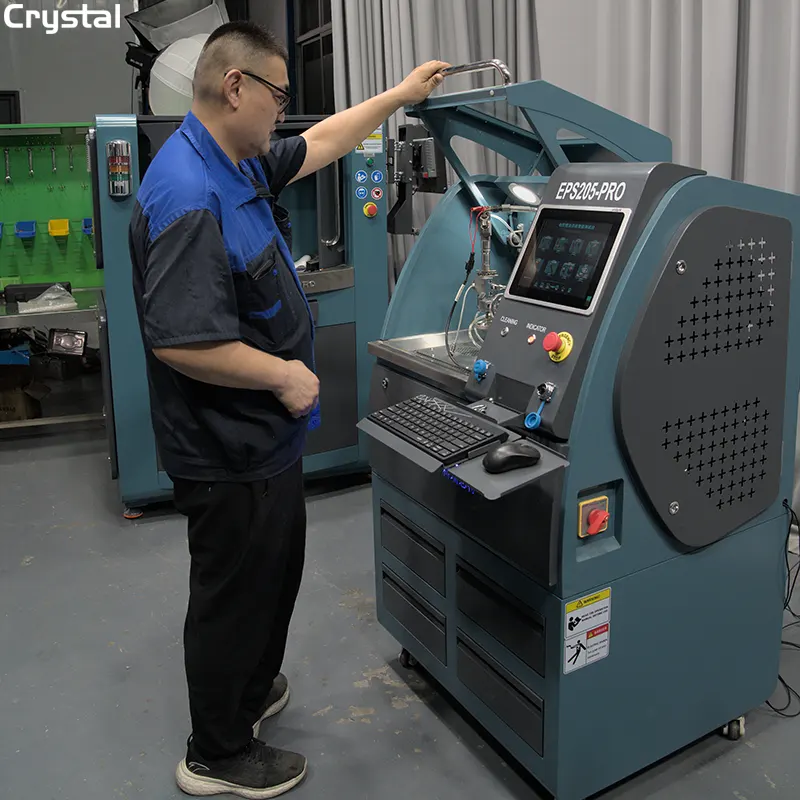
What the test bench generates:
- Comprehensive test report with pass/fail indicators for each parameter
- Calibration codes for ECU integration—including QR, IQA, IMA, ISA, c2i, c3i, and ICC (VD0)
- Data export for record-keeping and quality assurance
Data point: Modern Crystal test benches automatically generate correction codes during testing, enabling seamless ECU communication after injector replacement or servicing. The built-in database of over 4,000 injector data profiles allows instant comparison against OEM specifications.
Crystal Automation advantage: Crystal's common rail test benches feature fully automatic control systems that streamline the entire testing process—from high-pressure sealing tests to full-load injection measurements and response time analyses. The system supports testing for a wide range of electronically controlled injectors, including piezoelectric designs, and can handle thousands of different injector types.
Summary: The Complete Testing Sequence
| Step | Test | Key Parameters | Typical Values |
| 1 | Mounting & Preparation | Vertical positioning, lubrication | Brand-specific adapters |
| 2 | Electrical Verification | Capacitance, resistance, insulation | 0 – 12 μF capacitance |
| 3 | High-Pressure & Sealing | Pressure build-up, leak detection | Up to 2,600 bar, ±0.1 MPa |
| 4 | Minimum Pressure & Chatter | Needle movement threshold | OEM-specified minimum |
| 5 | Return Flow Measurement | Back leakage quantification | Compare to acceptable limits |
| 6 | Flow Rate & Timing | Delivery volume, response time | 0.1 ml accuracy, 100–5,000 μs |
| 7 | Report & Calibration Coding | QR, IQA, IMA, ISA, c2i, c3i, ICC | Automatic generation |
Why Accurate Piezoelectric Injector Testing Matters
Piezoelectric injectors were once considered non-repairable components due to the lack of dedicated testing equipment. Today, advanced common rail test benches have changed that reality.
The benefits of proper testing:
- Extended injector life – catch issues before they cause catastrophic failure
- Reduced downtime – diagnose accurately the first time
- Lower repair costs – replace only what's needed, not entire injectors
- Emissions compliance – ensure injectors meet tightening Euro 6/EPA standards
- Improved engine performance – restore power and fuel economy
Data point: Crystal Automation's test benches are exported to over 100 countries, reflecting the global demand for reliable, accurate diesel diagnostic equipment. Their multi-functional models—such as the CR918-PRO—can test piezoelectric injectors alongside electromagnetic injectors, HEUI injectors, EUI/EUP injectors, and pumps.
Conclusion
Testing piezoelectric injectors at pressures up to 2,600 bar requires precision, automation, and a systematic approach. These 7 essential steps—from proper mounting and electrical verification through flow measurement and calibration coding—ensure that every injector leaving your workshop meets OEM specifications.
With a high-quality common rail test bench from Crystal Automation, workshops can diagnose piezoelectric injector faults with confidence, reduce diagnostic time, and deliver right-first-time repairs that keep diesel engines running at peak performance.
Written by
Taian Crystal Automation Co., Ltd.
Editor Chen
www.crystalautotest.com
WhatsApp:+86 185 9528 8526
Email:martin@crystalautotest.com
- Top 6 High-Pressure Pump Diagnostic Methods on an Injection Pump Test Bench
- From Diagnosis to Repair: How Crystal Common Rail Test Benches Reduce Diesel Engine Downtime
- Two CR318Pro Common Rail Injector Test Bench Shipped Simultaneously to Italy - Made in China Earns Dual Recognition in the European Market
- Top 6 Steps to Diagnose Injection Pump Test Bench Flow Rate Inconsistency

Crystal Automation is a leading Chinese manufacturer of common rail test benches and fuel injector test benches.