Troubleshooting Common Faults on Injection Pump Test Bench
An injection pump test bench is the diagnostic backbone of any serious diesel workshop. It validates delivery volumes, verifies timing, and confirms that every pump leaving your shop meets OEM specifications. But when the test bench itself develops a fault, the consequences cascade: inaccurate readings, misdiagnosed pumps, wasted technician hours, and customers who return with the same problem they came in with.
The challenge is that test bench faults rarely announce themselves clearly. A drifting pressure reading might be a worn pump, a loose fitting, or a failing sensor. A fluctuating flow measurement might be air in the system, contaminated fluid, or a miscalibrated meter. Troubleshooting requires a systematic approach that isolates the variable before replacing the component.
This guide covers the most common faults on an injection pump test bench, their likely causes, and the diagnostic sequence that resolves them efficiently.
Fault 1: The Bench Will Not Build Pressure
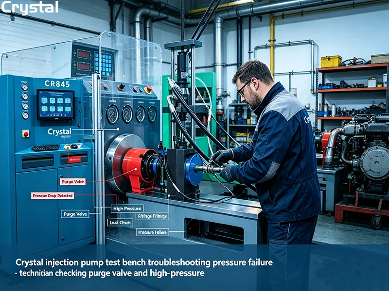
This is the most common and most disruptive fault. Without stable pressure, no meaningful test can be performed.
Likely Causes
The causes fall into three categories: leaks, air, and control valve issues.
- Loose or leaking fittings anywhere in the high-pressure circuit
- Open or leaking purge valve — a frequently overlooked cause
- Air entrained in the test fluid — air is compressible, hydraulic fluid is not
- Worn pump seals or plungers allowing internal bypass
- Faulty pressure regulating valve stuck open or worn
The Diagnostic Sequence
- Close the purge valve completely and verify it is seated. This is the fastest check and resolves a surprising number of cases.
- Inspect all fittings from the pump to the injector holder. A pressure drop of more than 2 bar per minute during a static test indicates a leak.
- Bleed the system with the bleed screws open until a steady stream of air-free fluid flows.
- Check the suction strainer — a partially blocked strainer causes cavitation, which introduces air.
- Perform a pressure decay test with the delivery valve blocked. If pressure still drops, the leakage is internal to the pump.
What the Data Tells You
A pressure drop from 350 psig to 250 psig in less than 30 seconds indicates internal leakage. Note that test fluid temperature affects this result: fluid above 80°F reduces the decay time, while fluid below 80°F increases it. Temperature must be controlled before interpreting the result.
Fault 2: Flow Readings Are Inconsistent or Inaccurate
Flow rate is the highest-weighted diagnostic parameter. When it becomes unreliable, every downstream decision becomes suspect.
Likely Causes
- Fuel leaks anywhere in the system, however minor
- Plugged or dirty test injectors and nozzles
- Air in the fuel system causing erratic delivery
- Clogged low-pressure oil circuit restricting supply
- Worn test nozzles altering spray and flow characteristics
- Flow meter drift or contamination
The Diagnostic Sequence
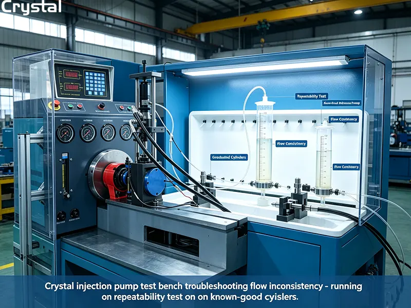
- Run a repeatability test on a known-good reference pump three times. If readings vary by more than 0.2–0.3 ml, the bench is the problem, not the pump.
- Check for leaks at every joint, fitting, and seal.
- Inspect and clean test injectors, checking orifice condition against the 0.020 in. (0.5 mm) specification.
- Bleed the system thoroughly.
- Verify test fluid temperature is held at 40 ± 2°C throughout the test.
- Calibrate or replace the flow meter if drift is confirmed.
What the Data Tells You
At full load, variation between pumping elements should not exceed 3 percent; at low idle, 12 percent. If your bench shows excessive variation on a pump that passes on another calibrated bench, the bench's flow system is the culprit.
Fault 3: Delivery Imbalance Between Cylinders
Individual cylinders showing significantly different delivery volumes is a classic fault with two possible origins: the pump or the bench.
Likely Causes
- Worn pumping element in one cylinder of the pump under test
- Loose column plug causing inconsistent delivery
- Dirt or debris in the delivery valve preventing proper sealing
- Damaged delivery valve gasket
- Worn test nozzle on one bench position
The Diagnostic Sequence
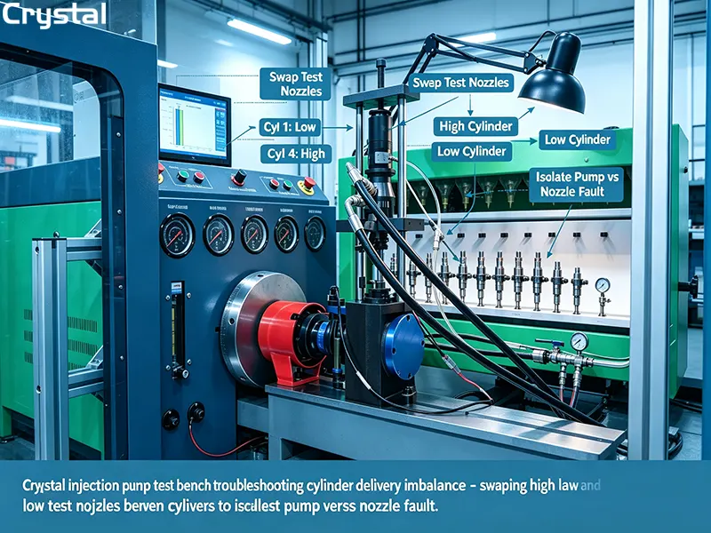
- Swap the high and low nozzles to different cylinders and rerun the test.
- If the variation follows the nozzle, the nozzle is the problem.
- If the variation stays with the cylinder, the pumping element is the problem.
- Inspect the delivery valve for dirt, sticking, or a damaged gasket.
- With the pump stationary, operate the transfer pump and remove the bleed screw. Continuous dripping indicates a stuck delivery valve or broken spring.
What the Data Tells You
This swap test is the single most efficient diagnostic step for delivery imbalance. It saves hours of unnecessary disassembly by distinguishing bench-side from pump-side faults in a single procedure.
Fault 4: Speed Instability Under Load
Flow rate is directly proportional to pump speed. If drive speed fluctuates, flow readings fluctuate with it.
Likely Causes
- Insufficient motor power for the test load
- Low voltage or phase loss in the electrical supply
- Faulty control box or frequency converter
- Worn drive coupling introducing backlash
- Loose or worn drive belts
The Diagnostic Sequence
- Verify the power supply — check voltage and confirm all three phases are present.
- Observe speed under load over 60 seconds. Fluctuation beyond ±10 RPM warrants investigation.
- Inspect the drive coupling for wear, backlash, or looseness.
- Check belt tension and condition.
- Verify the frequency converter is operating correctly.
What the Data Tells You
A speed fluctuation of 1 percent produces a flow fluctuation of approximately 1 percent—enough to push a borderline pump outside acceptable tolerances. Testing speed only at no-load is a common mistake; a bench that holds speed perfectly unloaded may fluctuate under load if the motor is undersized.
Fault 5: Electrical and Control System Faults
Modern test benches are as much electronic instruments as mechanical ones. Electrical faults can mimic mechanical problems and send technicians chasing the wrong component.
Likely Causes
- Voltage instability damaging components or causing erratic behavior
- Faulty instruments or sensors providing incorrect data
- Loose or corroded sensor connections
- Control software issues — bugs, outdated versions, corrupted files
- Solenoid or electromagnetic actuator failure
The Diagnostic Sequence
- Check the power supply and install a voltage stabilizer if fluctuations are common.
- Inspect instruments and connections — replace faulty gauges, repair damaged wiring.
- Verify sensor calibration against known references.
- Update or reinstall software to the latest version.
- Inspect electromagnetic actuators for connection and mechanical operation.
What the Data Tells You
Intermittent electrical faults are among the most time-consuming problems to diagnose. A five-minute visual inspection of connections can prevent hours of troubleshooting. Ground resistance should be verified at ≤4Ω.
Fault 6: Rapid Pressure Decay After Shutdown
Pressure that decays rapidly when the pump stops indicates internal leakage that must be isolated.
Likely Causes
- Internal leakage past worn plungers, damaged seals, or compromised delivery valves
- Leaking test injector allowing pressure to bleed off
- Loose or damaged blank nut from overtightening
- Purge valve not fully closed
The Diagnostic Sequence
- Check the average of three readings — if the average is outside specification, the bench needs rectification.
- Inspect all test injectors and rectify or replace as necessary.
- Tighten the injector fixing screw — a loose compression nut is a common cause.
- Verify the purge valve is fully closed.
- Inspect the blank nut and replace if damaged by overtightening.
What the Data Tells You
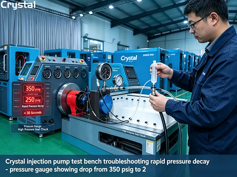
The pressure drop from 350 psig to 250 psig should take at least 30 seconds. A faster drop indicates leakage. This test is sensitive to fluid temperature, so temperature control must be verified before drawing conclusions.
A Systematic Troubleshooting Framework
The six faults above share a common diagnostic logic. Applying it consistently reduces mean time to repair.
Step 1: Isolate Bench from Component
Always determine whether the fault lies in the test bench or the pump under test. The reference pump and nozzle swap tests are the fastest way to make this distinction.
Step 2: Check the Simplest Causes First
Purge valve position, loose fittings, and fluid level resolve a disproportionate share of faults. Check them before disassembling anything.
Step 3: Verify the Measurement Conditions
Temperature, pressure stability, and speed stability must all be confirmed before interpreting any measurement. A reading taken under uncontrolled conditions is not a diagnostic result.
Step 4: Document and Trend
Record every fault, its cause, and the resolution. Over time, the trend reveals whether faults are random or systematic—and whether a component is approaching end of life.
Preventive Practices That Reduce Fault Frequency
Most test bench faults are preventable. The practices below address the root causes behind the six faults above.
- Daily fluid inspection catches contamination before it damages precision components
- Weekly filter cleaning prevents pressure instability and flow restriction
- Scheduled fluid and filter replacement — every 200 pumps or 2 months per Bosch specification
- Monthly pressure verification catches calibration drift at ±0.5 MPa
- Monthly standard injector verification at 17.5 ± 0.2 MPa opening pressure
- Monthly electrical inspection including ground resistance ≤4Ω
- Annual professional calibration restores factory specifications
The Crystal Automation Perspective
Crystal Automation's injection pump test benches are engineered to reduce fault frequency and simplify troubleshooting:
- 304 stainless steel fuel circuits resist corrosion and extend fluid life
- Three-stage filtration with 10-micron high-pressure filtration reduces contaminant-related faults
- Digital pressure displays enable quick verification without external gauges
- Frequency conversion speed regulation delivers stable speed under load
- Comprehensive electrical protection with auto-protecting functions
- Detailed manuals and training resources document diagnostic procedures
Crystal's platforms are exported to more than 100 countries, and the company's after-sales support emphasizes both preventive maintenance and efficient fault resolution.
Frequently Asked Questions
Why does my test bench fail to build pressure even after tightening all fittings?
Check the purge valve first. An open or leaking purge valve is one of the most frequently cited causes of pressure test failure. If the purge valve is confirmed closed, bleed the system for air and inspect the suction strainer for blockage.
How can I tell whether inconsistent flow readings come from the bench or the pump?
Run a repeatability test on a known-good reference pump three times. If readings vary by more than 0.2–0.3 ml across the three runs, the bench is the source. If the bench is repeatable but the customer pump is not, the pump is the source.
What does a delivery imbalance between cylinders indicate?
It indicates a fault in either a specific pumping element or a specific test nozzle. Swap the high and low nozzles to different cylinders and rerun the test. If the variation follows the nozzle, the nozzle is at fault; if it stays with the cylinder, the pumping element is at fault.
Why does pressure decay too quickly after the pump stops?
Rapid pressure decay indicates internal leakage—past worn plungers, damaged seals, or a compromised delivery valve. A drop from 350 psig to 250 psig in less than 30 seconds confirms leakage. Verify fluid temperature before interpreting the result, since temperature affects decay time.
How often should the test bench be calibrated to prevent these faults?
Pressure verification should be performed monthly, with immediate calibration if deviation exceeds ±0.5 MPa. Standard injector verification should also be monthly at 17.5 ± 0.2 MPa. A full professional calibration is recommended annually, or more frequently for high-volume workshops.
Conclusion
Troubleshooting an injection pump test bench is a discipline of isolation. The six faults covered here—pressure failure, flow inconsistency, delivery imbalance, speed instability, electrical faults, and rapid pressure decay—account for the majority of bench downtime. Each has a characteristic diagnostic sequence that distinguishes bench-side from pump-side causes before any component is replaced.
The workshop that masters these sequences does not merely repair faults faster. It prevents them, because the same systematic observation that resolves a fault also reveals the early warning signs that precede it.
Written by
Taian Crystal Automation Co., Ltd.
Editor Chen
WhatsApp:+86 185 5385 2072
Email:martin@crystalautotest.com
- Top Multi-Brand Common Rail Injector Test Bench: Can It Test Bosch, Denso, Delphi & Siemens?
- Top Common Rail Injector Test Bench Guide: Working Principle & 7 Key Testing Parameters
- Top 8 Differences: Injection Pump Test Bench vs Common Rail Test Bench
- Best Injection Pump Test Bench Buying Guide – 7 Questions Every Diesel Workshop Must Ask

Crystal Automation is a leading Chinese manufacturer of common rail test benches and fuel injector test benches.